Excitation Coil Model
Introduction
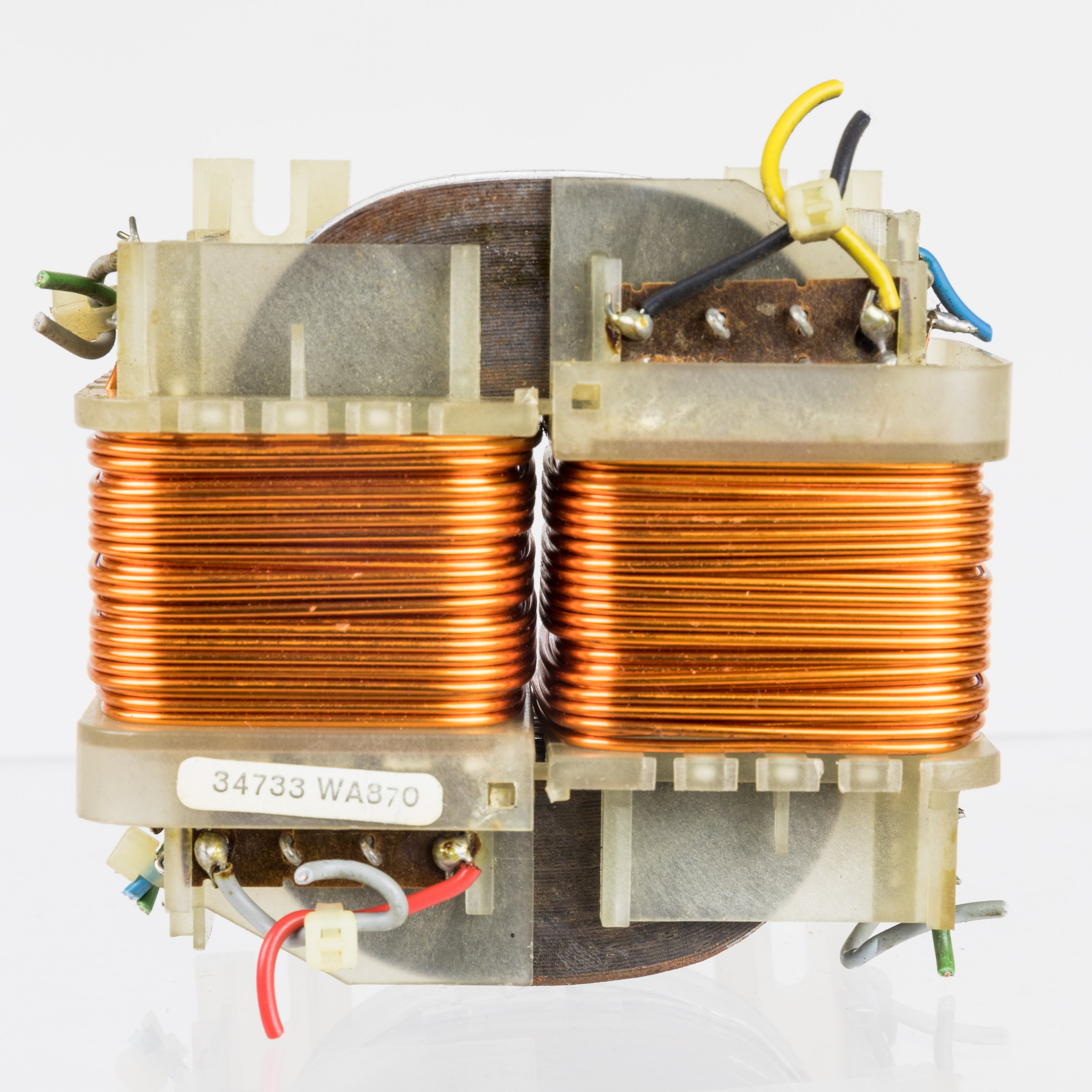
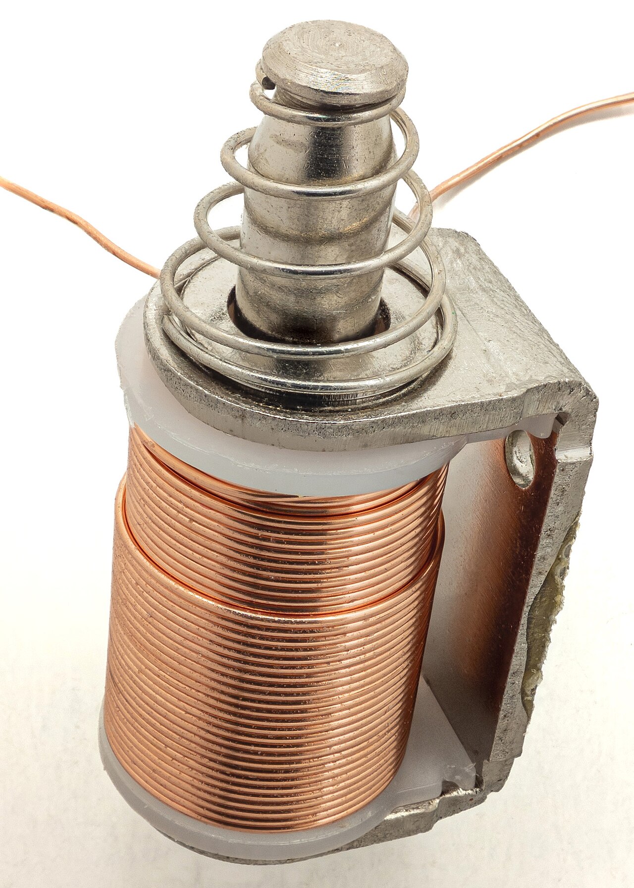
Electromagnetic devices such as motors, transformers, inductors, induction heaters, electromagnets, and MRI gradient coils widely use excitation coils. They generate magnetic fields by driving electric current through conductors.
The Excitation Coil is a support model for the Time-Domain Magnetic and Time-Harmonic Magnetic models: it supplies the divergence-free current density those models need on the right-hand side. A prescribed current, an applied voltage, or a circuit-coupled excitation can give the current density.
|
|
| Transformer with primary and secondary coils (CC BY-SA 4.0). | Solenoid coil of a linear actuator. |

To add an excitation coil model to a simulation:
from mufem.electromagnetics.coil import ExcitationCoilModel

coil_model = ExcitationCoilModel()
sim.get_model_manager().add_model(coil_model)
Coil Specification
You describe each coil with a CoilSpecification, which defines:
- Name — identifier of the coil
- Marker — the geometric region or boundary to which the coil applies
- Topology — whether terminals are open or closed
- Type — physical realization of the winding
- Excitation — how the coil is electrically driven
- Reverse Direction (optional) — part of the coil where current flows the opposite way
All but reverse_direction are required.
from mufem.electromagnetics.coil import CoilSpecification

coil = CoilSpecification(
    name="Coil",
    marker=my_coil_marker,
    topology=my_coil_topology,
    type=my_coil_type,
    excitation=my_coil_excitation,
)

coil_model.add_coil_specification(coil)
Topology
The topology specifies how the electrical circuit connects to the coil.
| Name | Description | Illustration |
|---|---|---|
| Open coil | The coil has electrical terminals. Current enters and leaves through designated boundary faces. | 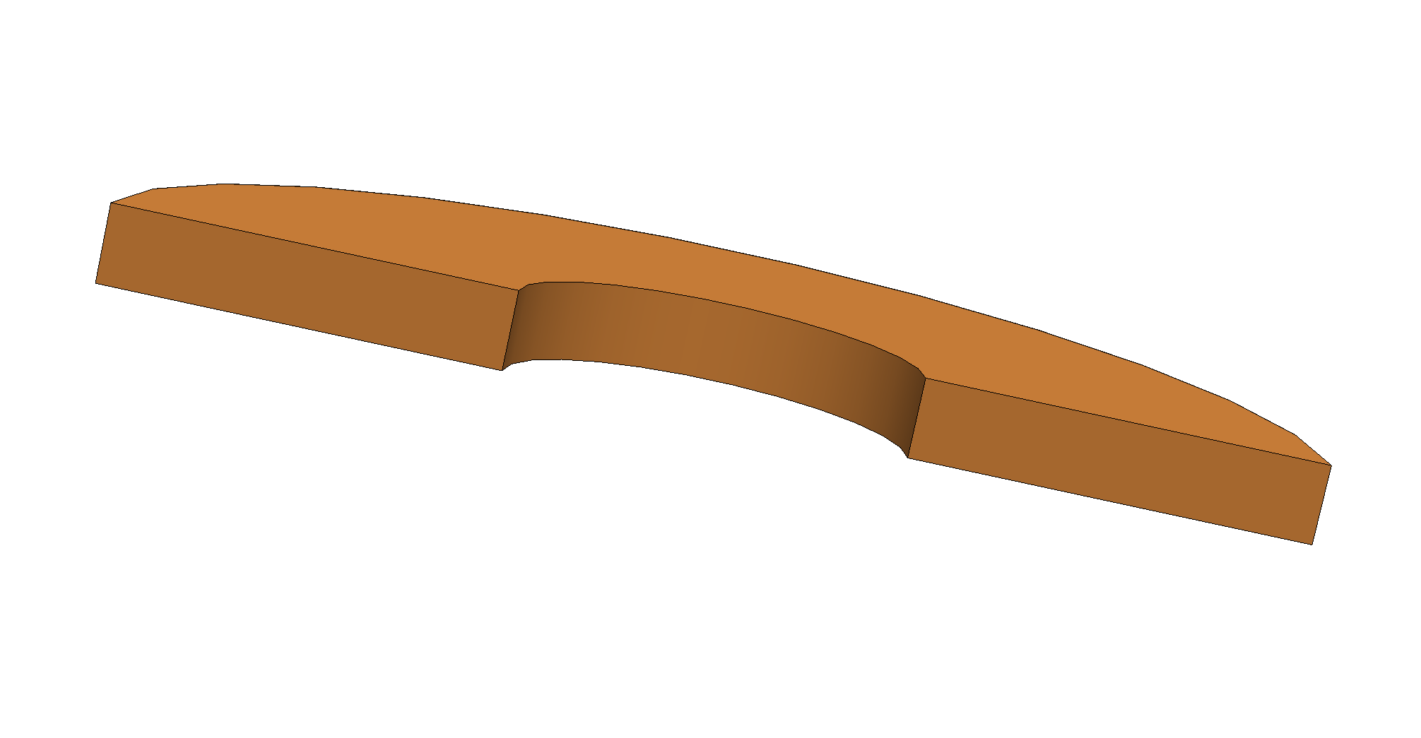 |
| Closed coil | The coil is electrically closed. Current circulates internally without terminals. | 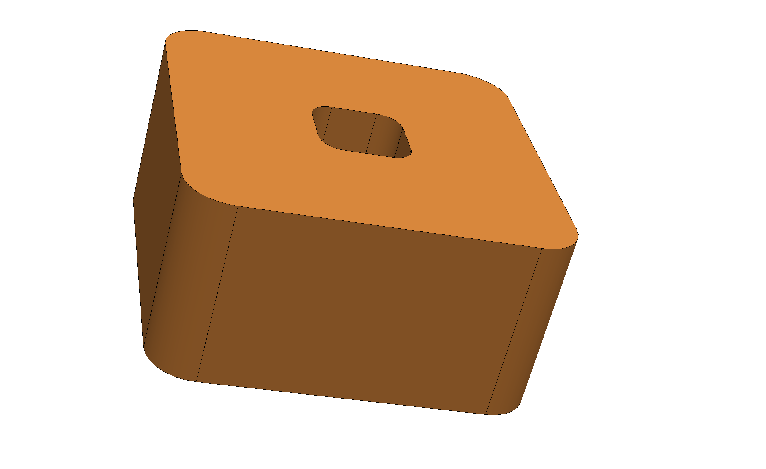 |
Type
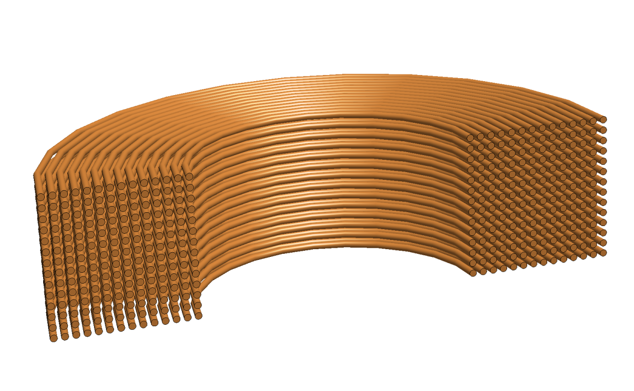
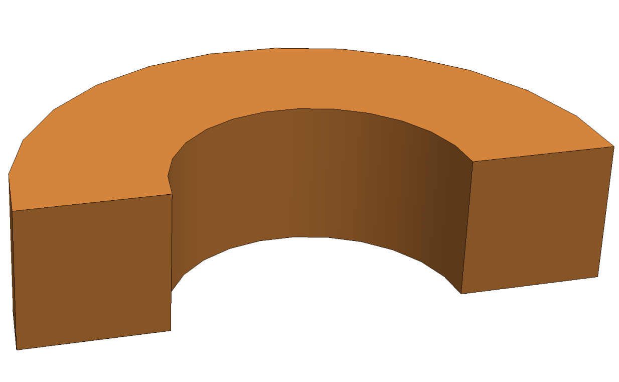
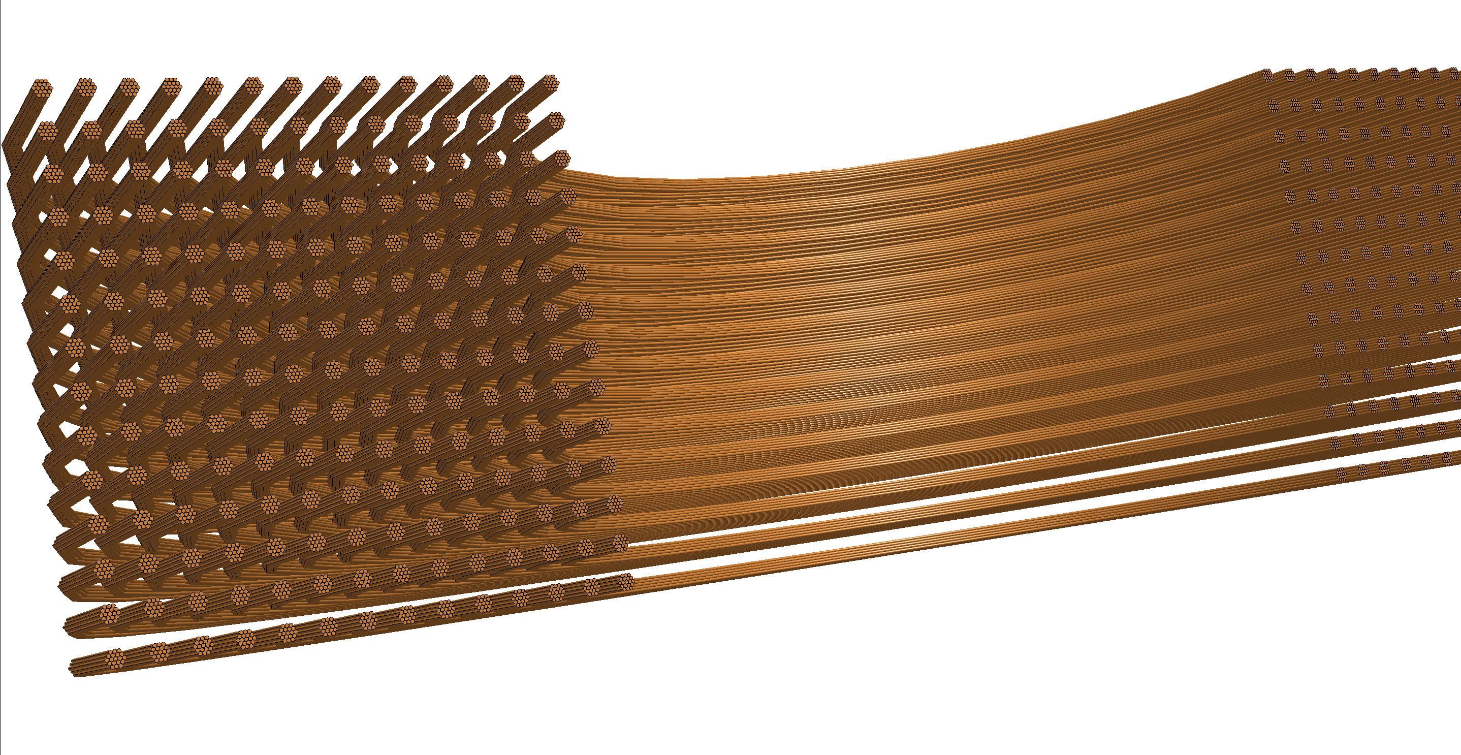
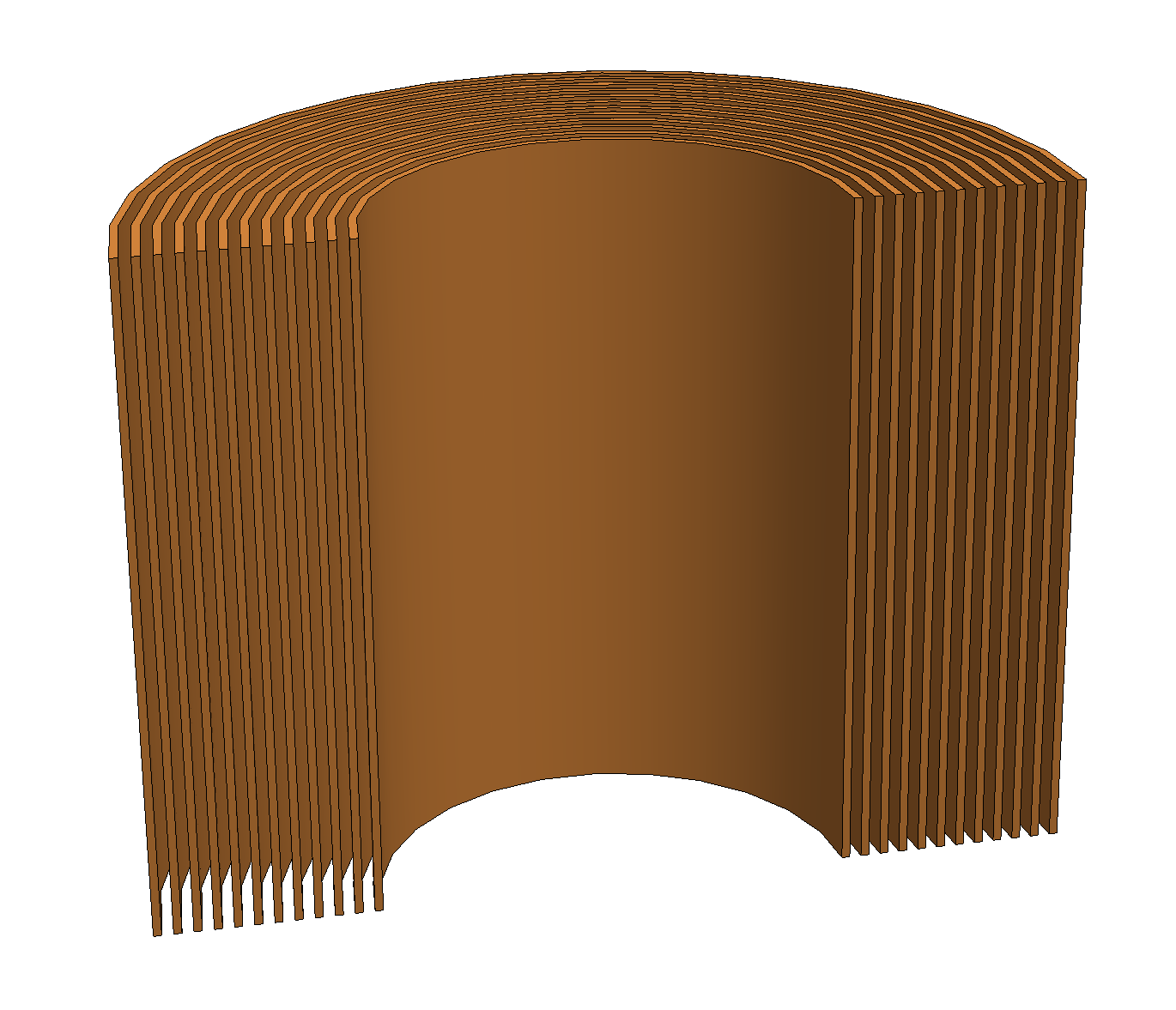
The type defines how the conductor is physically represented.
| Name | Description | Illustration |
|---|---|---|
| Stranded coil |
|
 |
| Solid coil |
|
 |
| Litz wire coil (not yet supported) |
|
 |
| Foil coil (not yet supported) |
|
 |
Excitation
An electrical source drives a coil. This source is either a prescribed terminal current or an applied voltage with a series resistance. Voltage excitation adds a circuit equation. This equation couples the coil current to the back-EMF that a time-varying field induces, and so gives realistic inductive loading.
| Name | Description | Illustration |
|---|---|---|
| Current excitation | The coil current is prescribed directly. | 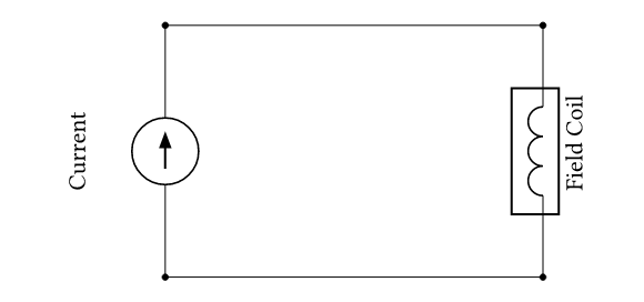 |
| Voltage excitation | A voltage is applied. Coil resistance and inductance determine the resulting current. | 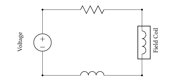 |
Reverse Direction
In a real winding the go side and the return side carry the same current
but in opposite physical directions along the wire. The optional
reverse_direction argument of CoilSpecification selects the cells where
the local conductor direction \(\boldsymbol{\hat{\tau}}\) should be flipped.
Everything that depends on direction — the driving current term, the flux linkage, and the current arrows shown in post-processing — picks up the sign automatically. You do not need to split the winding into two opposite specs or keep track of signs by hand.
Coil Groups
A real winding often consists of many separate conductor bodies. These
bodies all carry the same current. For example, one phase in a three-phase
motor has eight coil sides. You do not need to write one CoilSpecification
per body. Instead, describe the whole winding with a single specification.
Its marker covers every body at once, typically with a regex.
Each separate piece of conductor covered by such a marker is called a coil group. All groups in the same specification
- carry the same current (they are wired in series),
- share the same number of turns, topology, type, and excitation.
This collapses many near-identical specs into one and is the recommended way to describe distributed windings.
Constraint. The reverse_direction marker must be
uniform inside each coil group: one conductor cannot carry current in
two directions at the same time. If reverse_direction covers only part of
a group, the model raises an error.
Coefficients
The excitation coil model registers the following coefficients on the
CoefficientFunctionManager.
You can export them with the field exporter, or reference them in user
expressions to build custom integrands.
| Name | Field type | Description |
|---|---|---|
| Coil Direction | Vector | Unit vector along the local conductor direction, with the
reverse_direction sign already applied. NaN outside any
coil. |
| Coil Group | Scalar | Integer label identifying each separate conductor body of a
CoilSpecification. Numbering restarts per specification;
NaN outside every coil. |
| Coil Index | Scalar | Zero-based index of the CoilSpecification a cell
belongs to (matches the coil_index used by reports).
NaN outside every coil. |
Reports
The following reports are available. Some apply only to specific magnetic models, as noted.
| Name | Type | Description |
|---|---|---|
| Coil current | Scalar | Current in the coil (returns the applied current for current excitation, or the resulting current for voltage excitation). |
| Coil voltage | Scalar | Terminal voltage across the coil. |
| Coil resistance | Scalar | DC resistance computed from the conductor's electrical conductivity and the coil geometry. |
| Back EMF | Scalar | Back-EMF induced in the coil by the time-varying field. |
| Flux linkage | Scalar | Total magnetic flux linked with the coil. |
| Magnetic inductance | Symmetric matrix | Self- and mutual inductances of all coils (Time-Domain Magnetic model only). |
| Magnetic impedance | Complex matrix | Complex impedance matrix of the coil system (Time-Harmonic Magnetic model only). |
Example
Stator Phase Windings
A three-phase distributed winding with 4 slots per phase per side has 24
coil bodies marked Coil::+{U,V,W}::n and Coil::-{U,V,W}::n. With coil
groups and reverse_direction the three phases are described by three
specs:
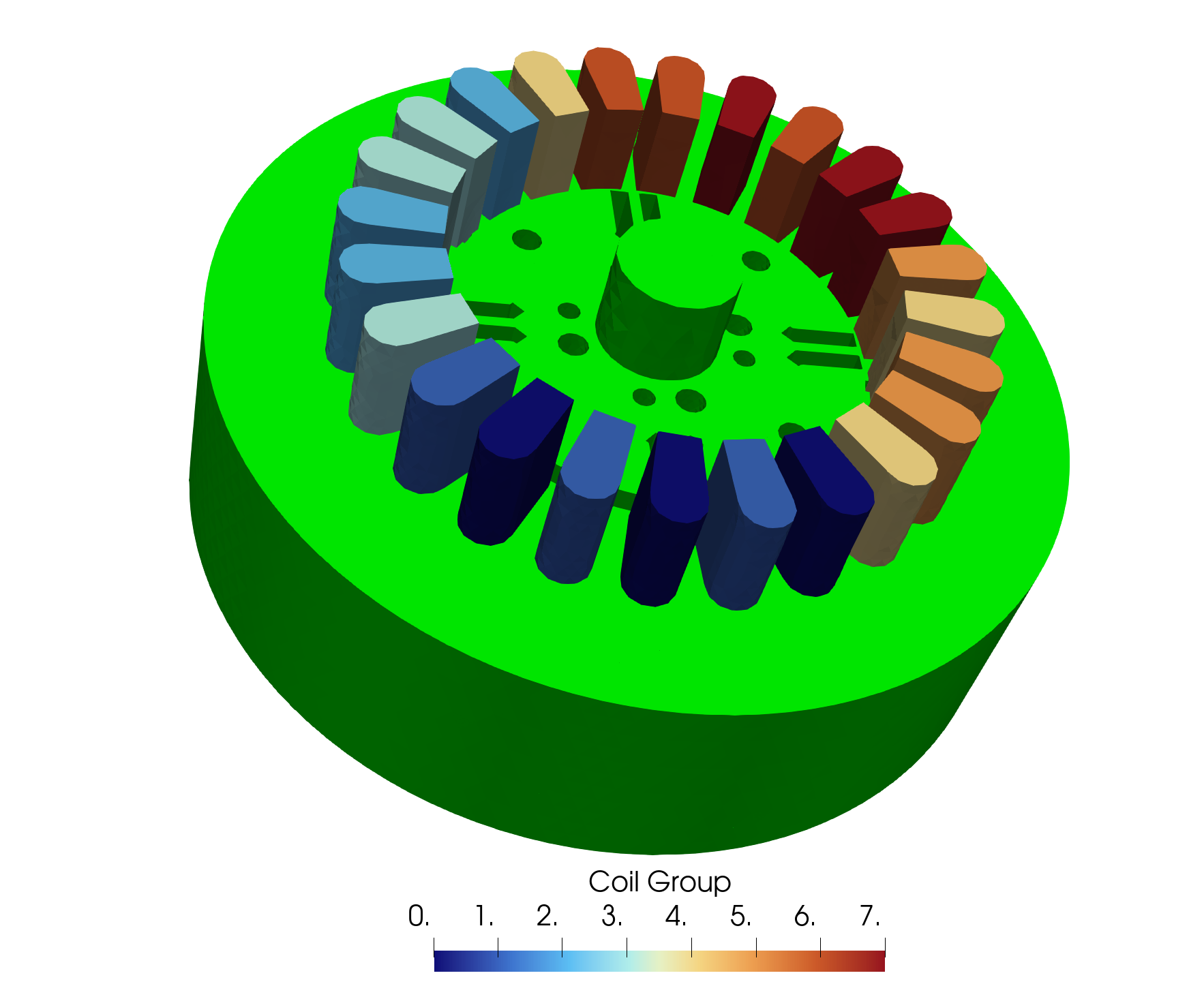
CoilSpecification per phase covers 8
disjoint sub-coils; the Coil Group coefficient labels
them \(0, 1, \dots, 7\).
from mufem import Bnd, CffSinusoidal, Vol
from mufem.electromagnetics.coil import (
    CoilSpecification,
    CoilExcitationCurrent,
    CoilTopologyOpen,
    CoilTypeStranded,
)

I_peak = 10.0      # A
frequency = 50.0   # Hz
phase_current = {
    phase: CffSinusoidal(amplitude=I_peak, frequency=frequency, phase=offset)
    for phase, offset in (("U", 0.0), ("V", -120.0), ("W", -240.0))
}

for phase in ("U", "V", "W"):
    coil = CoilSpecification(
        name=f"Coil::{phase}",
        marker=Vol(rf"Coil::[+-]{phase}::.*"),
        topology=CoilTopologyOpen(
            Bnd(rf"Coil::[+-]{phase}::.*::In"),
            Bnd(rf"Coil::[+-]{phase}::.*::Out"),
        ),
        type=CoilTypeStranded(number_of_turns=35),
        excitation=CoilExcitationCurrent(current=phase_current[phase]),
        reverse_direction=Vol(rf"Coil::\-{phase}::.*"),
    )
    coil_model.add_coil_specification(coil)
Each spec covers 8 disjoint sub-coils; current flows the opposite way in
the 4 Coil::-{phase}::.* slots, so a single MagneticFluxLinkageReport
over the spec yields the signed phase flux linkage \(\psi_\text{phase}\)
directly.