Coil Topology: Open Coil
Use an open coil when the electrical connections leave the simulation domain. This happens, for example, when you apply symmetry, or when solid coils have connectors that extend outside the modeled region.
This topology needs two ports:
- Entry port
- Exit port
For a positive current specification, the current flows from the entry port to the exit port. The resulting magnetic field orientation follows the right-hand rule.
Note that:
- Entry and Exit ports must be part of the coil volume.
- Degenerate ports (zero area or disconnected faces) are invalid.
When to use this
- Symmetric machine sections. A motor or transformer sector model where the coil is cut by a symmetry plane — the cut faces become the inlet / outlet ports.
- Bus-bars and solid conductors with terminals on the outer surface of the air box.
- Half- and quarter-models of any winding where the conductor leaves the simulation domain through a meshed face.
Examples
A solid coil named Coil has connectors that extend to the outer simulation domain. Blue marks the entry port named Coil::InputPort. Red marks the exit port named Coil::OutputPort.
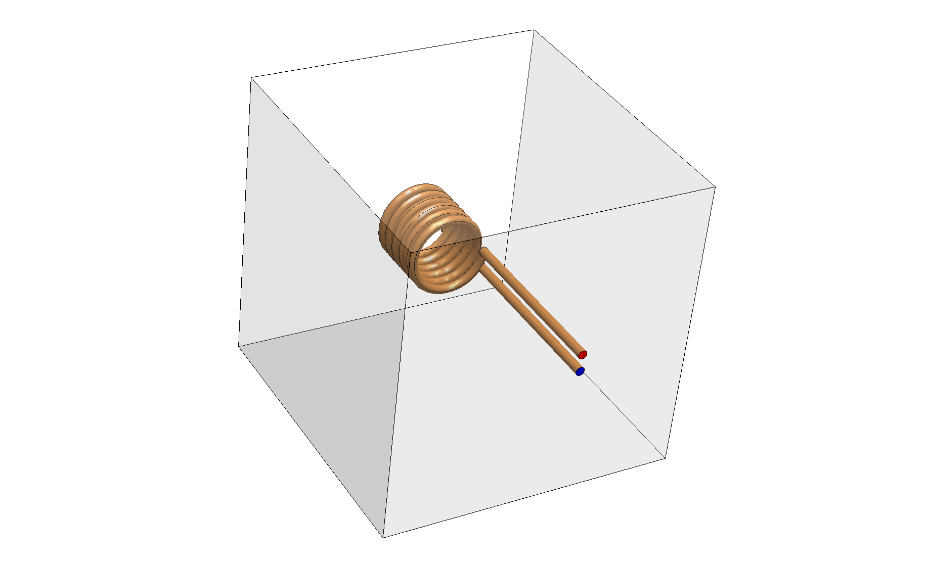
You can then define an open coil topology as: