Coil Type: Stranded Coil
A stranded coil is a coil wound from a conductor consisting of many thin insulated strands. Electrically, the winding path connects all strands in series, and they carry the same current.
In numerical models the model does not resolve the individual strands geometrically. Instead, a homogenized conducting body replaces the entire winding pack, with equivalent electromagnetic, thermal, and electrical behavior.
Stranded coils are the standard model for motor and transformer windings, small inductors, actuator solenoids, MRI gradient coils, and any multi-turn winding. In these windings the strand diameter stays smaller than the skin depth.
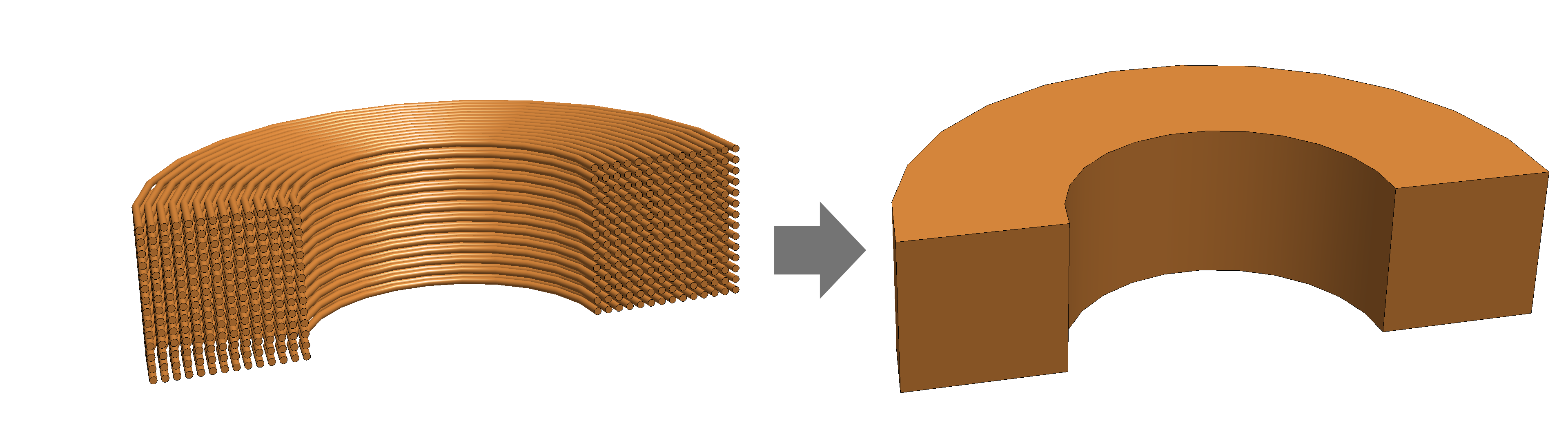
Although a stranded coil may geometrically resemble a solid coil, the physics are fundamentally different:
- The current density is amplified by the number of turns.
- The current density is uniform over each cross-section of the winding pack.
- Eddy currents are absent (no closed loops inside the conductor).
- Only a fraction of the cross-section conducts current → fill factor.
- Thermal and electrical properties become orthotropic (strong along the wire, weak across it).
Validity
This approximation is valid when the strand diameter is small compared to the skin depth. For example, consider a wound coil with a wire diameter of \(d=0.25\,\mathrm{mm}\) and an electric conductivity of \(5.8 \times 10^7\,\mathrm{S/m}\). At a frequency of \(f=1000\,\mathrm{Hz}\) the skin depth is $$ \delta_s = \sqrt{\frac{2}{\omega \mu \sigma}} = \sqrt{\frac{2}{ \left(2\pi \cdot 1000\,\mathrm{Hz}\right) \left(4\pi \cdot 10^{-7}\,\mathrm{H/m}\right) \left(5.8 \times 10^7\,\mathrm{S/m}\right) }} \approx 2.1\,\mathrm{mm}, $$ which is larger than the diameter of the wire. This means that the current remains uniform inside each strand to a very good approximation. This reduces the computational cost by several orders of magnitude while preserving correct global behavior.
Electric Current Homogenization
The homogenization of the coil needs certain adaptations. Consider the front face of the stranded coil shown in Figure 1.
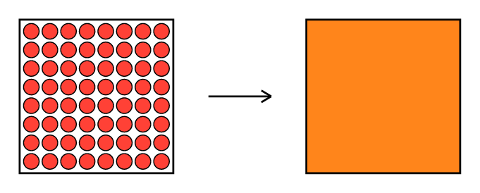
If each strand carries a current \(I\), then across the coil cross-section we have an averaged electric current density given by $$ j_z = \frac{N_t I}{S_c} \quad, $$ where \(I\,[\mathrm{A}]\) is the applied current, \(N_t\) is the number of turns, and \(S_c\,[\mathrm{m}^2]\) is the cross-section of the coil.
We further introduce the fill factor \(n_f\) of a stranded coil given by $$ n_f = \frac{S_\text{ws}}{S_c} \quad, $$ where \(S_\text{ws}\) is the total wire cross-section area. mufem assigns the raw conductor conductivity \(\sigma_\text{ws}\) to the homogenised region. The fill-factor correction enters the Ohmic-loss integrand. So the effective dissipation density is $$ P_\Omega = \frac{|\mathbf{J}|^2}{n_f\,\sigma_\text{ws}} \quad, $$ where \(\mathbf{J}\) is the homogenized electric current density. You supply the correction separately through the wire specification. Without one it defaults to \(n_f = 1\) (no correction).
Wire Specification
You supply the fill factor \(n_f\) — the fraction of the bundle cross-section
actually occupied by copper — to CoilTypeStranded with the optional
wire_specification argument. Three equivalent forms are available. Pick
the one that best fits your data (manufacturer datasheet, CAD geometry, or
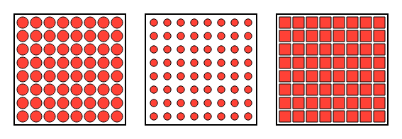
measured copper fraction). Figure 3 shows the geometric picture behind the
three forms.
| Class | Argument | Effective \(n_f\) | When to use |
|---|---|---|---|
StrandedWireSpecificationFillRatio |
fill_ratio (dimensionless, \(0 < n_f \le 1\)) |
\(n_f\) given directly | When only the bulk copper-to-bundle ratio is known (datasheet, measured) and the bundle cross-section is roughly uniform along the coil. |
StrandedWireSpecificationWireDiameter |
wire_diameter \([\mathrm{m}]\) |
\(n_f(x) = N_t\,\pi(d/2)^2\,/\,S_c(x)\) | For round wires of known diameter — the common case for magnet wire. Stays accurate when the bundle tapers along the coil. |
StrandedWireSpecificationWireCrossSection |
wire_cross_section \([\mathrm{m}^2]\) |
\(n_f(x) = N_t\,A_\text{wire}\,/\,S_c(x)\) | For non-circular wires (rectangular bar conductors, custom strand shapes) where the diameter is not a meaningful input. Stays accurate when the bundle tapers along the coil. |
where \(N_t\) is the number of turns and \(S_c(x)\) the local bundle cross-section.
If you give no wire specification, \(n_f \equiv 1\) and mufem applies no fill-factor correction.
Note
The fill factor enters the coil resistance and so the Ohmic heating: lower \(n_f\) means less copper carrying the current, so the resistance rises as \(1/n_f\) and the dissipated power \(P_\Omega = |\mathbf{J}|^2 / (n_f\,\sigma_\text{ws})\) rises with it. Without a wire specification both quantities are reported as if the bundle were fully copper.
Example
A bare stranded coil with no fill-factor correction:
from mufem.electromagnetics.coil import CoilTypeStranded

coil_type = CoilTypeStranded(number_of_turns=280)
The same coil with a 70 % copper fill ratio:
from mufem.electromagnetics.coil import (
    CoilTypeStranded,
    StrandedWireSpecificationFillRatio,
)

coil_type = CoilTypeStranded(
    number_of_turns=280,
    wire_specification=StrandedWireSpecificationFillRatio(fill_ratio=0.7),
)
Same coil, but specified through the physical wire diameter (\(d = 0.5\,\mathrm{mm}\)):