Lamination Module
The Lamination module addresses the modelling of laminated ferromagnetic cores — stacks of thin ferromagnetic sheets separated by insulating interlayers. This is the standard core construction in power and distribution transformers, induction motors, generators, reactors, and inductors.
Why laminations?
A solid ferromagnetic core exposed to a time-varying magnetic flux develops eddy currents. These currents close in the bulk and dissipate a significant fraction of the throughput power as ohmic loss. Cut the core into thin sheets oriented along the dominant flux direction and electrically isolate the sheets from each other to interrupt these loops. The eddy-current path is then restricted to the cross-section of a single sheet, and the per-unit-volume loss drops roughly as \(d^2\), where \(d\) is the sheet thickness. Typical sheet thicknesses for power applications are \(0.2\)–\(0.5\,\mathrm{mm}\) (grain-oriented or non-oriented silicon steel for mains-frequency transformers and motors) down to a few tens of micrometres for high-frequency cores.
A mesh that resolves every sheet is prohibitive for industrial cores, which typically carry \(10^3\)–\(10^4\) sheets. So the module treats the stack as an anisotropic continuum and adds a sheet-scale correction that recovers the in-sheet eddy-current losses lost in the homogenisation.
Physical picture
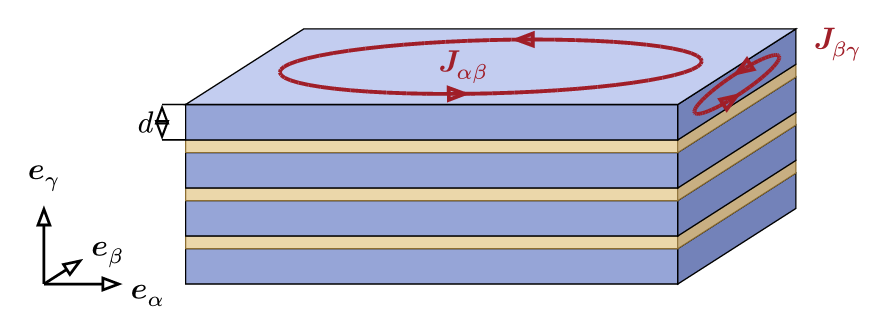
The local frame \(\{\vec{e}_\alpha, \vec{e}_\beta, \vec{e}_\gamma\}\) has \(\vec{e}_\gamma\) along the stack and \((\vec{e}_\alpha, \vec{e}_\beta)\) in the lamination plane. A laminate has these properties:
- the stacking direction \(\vec{e}_\gamma\) — unit vector normal to the sheets,
- the sheet thickness \(d\) of a single ferromagnetic layer,
- the stacking factor \(F \in (0, 1]\) — volume fraction of the magnetic phase (the remaining \(1-F\) is the insulator),
- the sheet's magnetic permeability \(\mu\) and electric conductivity \(\sigma\).
Two eddy-current channels arise in the stack:
| Channel | Driven by | Current direction | Closes in |
|---|---|---|---|
| \(\vec{j}_{\alpha\beta}\) | \(\partial_t \vec{B}_\gamma\) — flux normal to the sheets | lamination plane | the macroscopic stack, on length scales \(\gg d\) |
| \(\vec{j}_{\beta\gamma}\) | \(\partial_t \vec{B}_\alpha\) — flux parallel to the sheets | within a single sheet, with a linear \(\gamma\)-profile | one sheet |
The first channel survives the homogenisation, and an anisotropic continuum captures it. The second is sub-grid by construction. You must add it back with a sheet-scale correction.
Contents
The module currently gives one material per magnetic model. Both implement the homogenised continuum plus the first-order in-sheet eddy-current correction.
| Magnetic model | Material class | Page |
|---|---|---|
| Time-Domain Magnetic | TimeDomainMagneticLaminationMaterial |
Laminated Material |
| Time-Harmonic Magnetic | TimeHarmonicMagneticLaminationMaterial |
Laminated Material |