Matching Interface Condition
The matching interface condition stitches two boundaries \(\Gamma_0\) and \(\Gamma_1\) together so that the magnetic vector potential \(\mathbf{A}\) is continuous (or sign-flipped) across the interface.
The geometric matching maps side-1 onto side-0 by a rigid transform
where \(\mathbf{R}\) is an orthogonal \(3 \times 3\) matrix (rotation or reflection) and \(\mathbf{t}\) a translation vector. The orientation-aware HCurl coupling supports any orthogonal \(\mathbf{R}\), so you can express rotational sectors, periodic cells, and anti-periodic sectors directly.
Two symmetry modes are available:
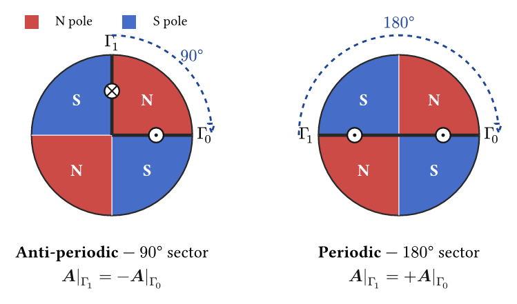
- Periodic (
InterfaceSymmetry.PERIODIC) — the field is identical on both sides. Use for full-period sectors (one pole-pair of a motor, a full lattice cell, and so on). - Anti-periodic (
InterfaceSymmetry.ANTI_PERIODIC) — the field reverses sign across the interface. Use for half-period sectors with alternating polarity (one pole pitch of a motor, a Halbach slab with alternating magnetization, and so on).
Applicability
Applicable to a pair of boundary markers — one per side — that map onto each other under the rigid transform \(\mathbf{T}\). The rotation \(\mathbf{R}\) must be orthogonal. The condition couples the matched HCurl degrees of freedom (continuously for periodic, sign-flipped for anti-periodic). It does not model imperfect or partial coupling.
When to use this
- Rotating machinery sector models. Solve one pole or one pole-pair of a synchronous machine, induction motor, or generator instead of the full \(360°\) — typically a \(4{-}10\times\) reduction in unknowns.
- Periodic Halbach arrays and linear motors. A single sector with anti-periodic stitching reproduces an infinite alternating pattern.
- Bulk lattices. Periodic unit cell of a structured material (for example a laminated stack viewed in plane) with translation-only matching.
Usage
A periodic boundary condition between two parallel faces separated by a translation vector:
from mufem.electromagnetics.timedomainmagnetic import (
    InterfaceSymmetry,
    MatchingInterfaceCondition,
)

periodic_bc = MatchingInterfaceCondition(
    name="Periodic",
    marker0="Cell::Left" @ Bnd,
    marker1="Cell::Right" @ Bnd,
    symmetry=InterfaceSymmetry.PERIODIC,
    translation=(-1.0, 0.0, 0.0),
)

time_domain_magnetic_model.add_condition(periodic_bc)
A \(22.5°\) anti-periodic stitch (one sector of a 16-pole Halbach cylinder) around the \(z\)-axis:
import math

c = math.cos(math.pi / 8)
s = math.sin(math.pi / 8)

rotation_neg_22_5_z = [
    [ c,  s, 0.0],
    [-s,  c, 0.0],
    [0.0, 0.0, 1.0],
]

anti_periodic_bc = MatchingInterfaceCondition(
    name="AntiPeriodic",
    marker0="AntiPeriodic::Phi_0" @ Bnd,
    marker1="AntiPeriodic::Phi_22_5" @ Bnd,
    symmetry=InterfaceSymmetry.ANTI_PERIODIC,
    rotation=rotation_neg_22_5_z,
)

time_domain_magnetic_model.add_condition(anti_periodic_bc)
The rotation matrix must map vertices of marker1 into the frame of
marker0. Translation defaults to no translation; rotation defaults to the
identity.